Performance review
Passive cooling design measures in roofs
Attic rooms and other habitable spaces directly under the roof can often feel warm, almost unbearably so at times. As fifty percent of a building’s external heat gain is generated and accumulated
through the roof,
numerous experimental and analytical studies have been performed, in attempts to decrease that heat load. Solutions such as mechanical cooling systems incorporated into buildings provide us with the means to mitigate this problem, but they need not be the only response to the issue. Passive cooling design measures can be introduced into the building’s design to help bring down indoor temperature and improve thermal comfort, without necessitating mechanical cooling systems, which can sometimes be cost inefficient. Consideration given to basic materials used for roofing and insulation can help to reduce the accumulated heat load, without additional frills.
In this article, we document the results of performance reviews conducted on the various roofing details and materials in three of our completed projects. A sling psychrometer was used to measure the temperature of the indoor and outdoor spaces. Consisting of a dry bulb thermometer and wet bulb thermometer, the psychrometer was swung for about a minute to obtain the ambient temperature as accurately as possible. As a baseline comparison, we documented an apartment unit with a typical Reinforced Concrete (RC) flat roof without false ceiling or insulation. We recorded a decrease of 1.5°C between the indoor and outdoor dry bulb temperature.
Based on these measurements, we determined that the three case studies all achieved a level of passive cooling, with the recorded decrease from indoor to outdoor dry bulb temperature varying between 3°C and 4°C. Below, we delve deeper into each case study, and how each roof system was designed to manage thermal comfort within habitable space, while adhering to the project's specific needs and approaches.
CASE STUDY A: RC ROOF & TERRACOTTA CLADDING WITH VENTILATED AIR GAP IN-BETWEEN

The first case study is a three-and-a-half storey housing cluster, comprising two bungalows and 2 semi-detached houses. Each individual housing unit utilises a terracotta cladding system as the roof treatment, because of its low thermal conductivity and UV-resistant properties. Terreal Terracotta, being a ventilated roof system, is installed with an air gap layer in between the cladding and the RC roof, which allows for a constant, passive air flow that dissipates heat through the gaps.
The cladding acts as a second skin to the RC roof layer, and together with its thermal insulation advantages, gave us a significant recorded indoor vs outdoor temperature reduction of 4°C, which is approximately two times the recorded thermal difference of a normal RC flat roof.
The cladding acts as a second skin to the RC roof layer, and together with its thermal insulation advantages, gave us a significant recorded indoor vs outdoor temperature reduction of 4°C, which is approximately two times the recorded thermal difference of a normal RC flat roof.

ISO DETAIL OF RC ROOF AND TERRACOTTA CLADDING

SECTION DETAIL OF RC ROOF AND TERRACOTTA CLADDING
The roof anatomy starts with the terracotta cladding as its first external layer. The cladding’s mounting profiles were secured directly onto the RC pitched roof, which was cast in-situ. The profiles elevated the terracotta tiles to create an airflow gap of approximately 75mm, which also allows for water to run off the pitched roof. Using a clip system, the tiles were easily fastened, and the heat accumulated on the RC roof dissipates through the gaps with the tiles. An additional gypsum board false ceiling layer under the RC roof helps to increase thermal insulation for the internal spaces. The terracotta tiles were similarly applied onto the walls of the third storey, to further reduce heat gain and to create a consistent language with the roof form.
CASE STUDY B: RC ROOF & FALSE CEILING WITH VENTILATED AIR WELL

Case Study B is a two-and-a-half storey intermediate terrace house. Sandwiched between two solid parti walls, the house's site conditions imposed the particular challenges of maximizing daylight and creating natural ventilation in the internal spaces.
Due to budget and timeline constraints, a simple RC grid structure was conceived for Case Study B. RC columns and beams, infill brick walls and flat slabs make up the anatomy of the house. Circulation and activities revolve around a central airwell in the middle of the plan, which extends all the way up to the roof of the house. This airwell allows daylight to fill the intermediate spaces of levels below through a glass skylight.
Due to budget and timeline constraints, a simple RC grid structure was conceived for Case Study B. RC columns and beams, infill brick walls and flat slabs make up the anatomy of the house. Circulation and activities revolve around a central airwell in the middle of the plan, which extends all the way up to the roof of the house. This airwell allows daylight to fill the intermediate spaces of levels below through a glass skylight.

ISO DETAIL OF RC ROOF AND FALSE CEILING

SECTION DETAIL OF RC ROOF AND FALSE CEILING
Rooms on the uppermost floor relate directly to the airwell, harnessing it to reduce accumulated heat and introduce natural ventilation. Both the bedroom and bathroom on either side has windows which open and ventilate out directly into the airwell. Aluminium grilles were installed in slots within the roof beams at the false ceiling level, allowing heat collected in the false ceiling layer to dissipate out through the louvers above. As hot air also rises up the airwell from the lower levels, thermal heat is constantly being drawn out of the house, which resulted in a recorded 3°C drop between outdoor and indoor dry bulb temperature.

Ventilation louvers in false ceiling (below) & ventilation louvers for air well hot air to dissipate
Central air well with ventilation louvers allow for hot air to dissipate.
CASE STUDY C: METAL ROOF & FALSE CEILING WITH VENTILATED AIR GAP IN-BETWEEN

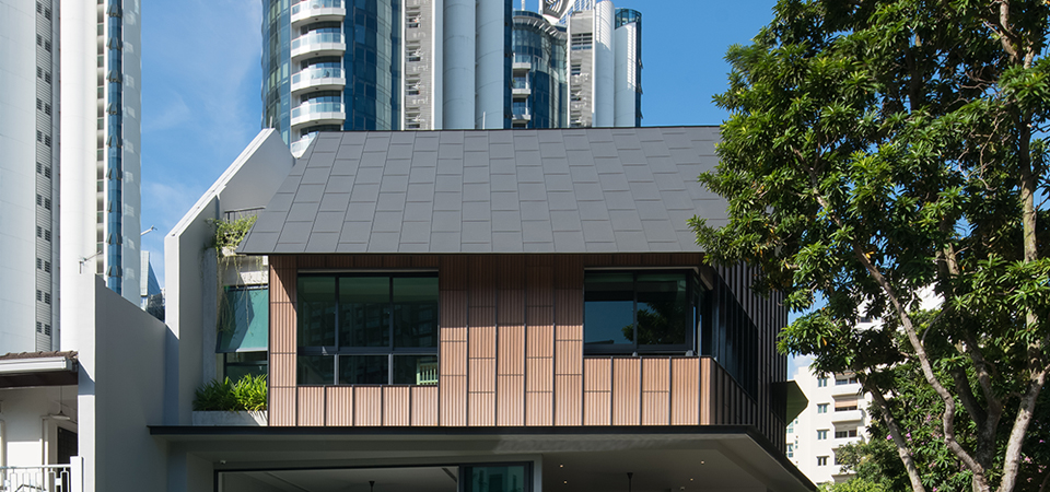
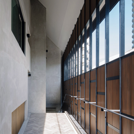
Case Study C is a two-and-a-half storey semi-detached dwelling with a basement. The building primarily utilises a vernacular solution for managing the local tropical climate: a series of connected verandas links spaces together as it circulates around the perimeter. In this way, a naturally ventilated volume of living spaces is created, with continuous passive cross ventilation. This additional veranda layer separates internal and external spaces, helping to reduce the building's thermal load, ultimately contributing to improved thermal comfort through passive cooling measures.

ISO DETAIL OF METAL ROOF AND FALSE CEILING, AIR FLOW IN BLUE

SECTION DETAIL OF METAL ROOF AND FALSE CEILING
The roof form primarily comprises two pitched metal roofs with rockwool insulation installed underneath for an additional layer of thermal protection. An RC flat roof bridges the two metal roofs, creating a recess between the two pitches where ventilation louvers can be installed without being seen from the main façade. Similar to Case Study B, the louvers allow for heat to be dissipated easily through an air gap between the roof and false ceiling, while protecting the internal spaces from rain.
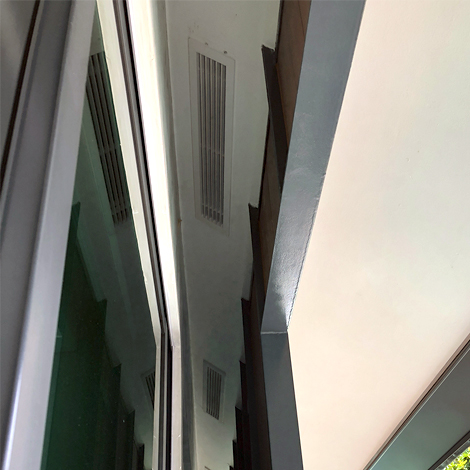
On the lower end of the pitched roofs, a series of aluminium grilles is mounted at the false ceiling in the veranda corridors. As hot air rises, aided by the cross ventilation breeze, air is constantly pushed through the grilles and the air gaps between the metal roofs and false ceilings. This continuous cross-airflow above the ceiling helps to constantly cool the rooms below. A temperature decrease of 4°C was recorded in the internal space.
On the lower end of the pitched roofs, a series of aluminium grilles is mounted at the false ceiling in the veranda corridors. As hot air rises, aided by the cross ventilation breeze, air is constantly pushed through the grilles and the air gaps between the metal roofs and false ceilings. This continuous cross-airflow above the ceiling helps to constantly cool the rooms below. A temperature decrease of 4°C was recorded in the internal space.

Ventilation louvers at false ceiling

Veranda-like naturally ventilated corridors
IN SUMMARY...
Here is a quick comparison between the roof anatomies of the case studies and a baseline simple RC flat roof.
| BASE | CASE STUDY A | CASE STUDY B | CASE STUDY C | |
| TYPE OF ROOF |
RC FLAT ROOF |
RC PITCHED ROOF WITH CLADDING & FALSE CEILING |
RC FLAT ROOF WITH FALSE CEILING |
METAL ROOF WITH FALSE CEILING |
|
KEY ROOF LAYERS |
-RC ROOF |
- TERRACOTTA ROOF TILES - PURLINS W/ AIR GAP BELOW - RC ROOF - GYPSUM BOARD CEILING |
- METAL ROOF/ GLASS SKYLIGHT - LOUVERS @ AIRWELL - RC ROOF - LOUVERS @ FALSE CEILING - GYPSUM CEILING BOARD |
- METAL ROOF - ROCKWOOL INSULATION - LOUVERS @ FALSE CEILING W/ AIR GAP - GYPSUM CEILING BOARD |
| DIFFERENCE IN INDOOR & OUTDOOR TEMPERATURE |
1.5°C | 4.0°C | 3.0°C | 4.0°C |
WHAT'S NEXT?
With the advancement of technology in building science and the relative ease of implementation, cooling indoor spaces through mechanical means has become the norm. Such methods, however, not only result in potentially large construction costs and downstream cost inefficiency, but also impede ongoing efforts towards sustainability in buildings. Taking cues from vernacular ways of heat management before the widespread use of mechanical cooling, simple and inexpensive design solutions can be implemented in a building, using passive cooling to reduce heat gain and bring thermal comfort to a desirable level. The reviews conducted for this article indicate the potential of further developing passive cooling techniques as easily implementable strategies in building construction. As an ongoing study across future projects, we aim to further refine our strategies for passively achieving comfortable habitable temperatures, and reduce the reliance on mechanical cooling systems.
BEST WHEN TAKEN WITH A PINCH OF SALT.
PLEASE EMAIL FARMACY@FARM.SG WITH YOUR FEEDBACK, OR IN CASE OF ANY INACCURACIES.
PLEASE EMAIL FARMACY@FARM.SG WITH YOUR FEEDBACK, OR IN CASE OF ANY INACCURACIES.
REF. NO.
PROTOTYPES-002-ROOF-PASSIVE-COOLING-REVIEW
CONTRIBUTOR(S)
CLIFFORD SEE, LEE HUI LIAN, TAN QIAN ROU
PUBLISHED
31.12.18